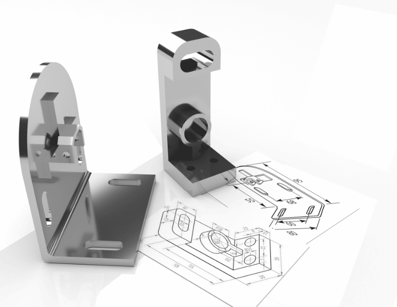
The drawing of drawings is an integral part of the product development process, which uses a standardised language and symbols to communicate accurately and visually the information necessary for the manufacture of a part or product.
Before any product can take shape in reality, it requires the design of drawings for each of its parts.
In this article we explain what a part drawing is, what it consists of and the importance of its usefulness.
What is a part drawing?
A part drawing is called a production drawing if it facilitates its manufacture.
The part drawing is an authorised drawing and document used to produce the designed component. It indicates all dimensions, limits and special finishing processes such as heat treatment, grinding, etc., as well as the material used.
Similarly, it must mention the number of parts needed to manufacture the assembled unit of which the piece is a part. It should also indicate the sub-assembly or main assembly where it will be assembled and verify the technical feasibility of the product to be built and the correct functioning of the design.
In this sense, it is necessary to prepare the manufacturing drawing of each component on a separate sheet, since each component is manufactured one at a time.
In short, the design drawing is a technical drawing that shows the shape, structure, dimensions, tolerances, accuracy and other requirements of a part in plan form. It helps define the requirements of an engineering part and conveys the design concept.
The importance of drawing plans
All construction or fabrication begins as an idea in the mind of a designer and is captured on paper.
Plan drawing is a technique used to represent a three-dimensional object on two-dimensional drawing paper. In this sense, it provides an accurate representation of the object and shows all parts in their true size relationship. In this way, the draftsman converts a sketch into a detailed drawing that everyone can understand in the same way, as the drawings speak in a universal language of lines and symbols.
Engineers use plan drawing to convey information about a particular object. Since even the most basic components require many drawings to describe them completely.
Single-part drawing provides a visual representation of the structure, dimensions, tolerances and other requirements of a part. This is essential in the manufacturing industry, where the single-part drawing is often used as a processing unit.
The shape and size of an object must be known before it can be built. Therefore, an engineering drawing is needed to represent the shape of the object, its dimensions and other relevant data.
Strategic design, of which drawing design is a part, aims to create better and more efficient products. To this end, the creation of drawings is used during the design and prototyping phases, so as to ensure that the idea can be executed and function as intended.
On the other hand, an engineer can make use of an assembly drawing to show a machine or equipment being assembled from several parts to achieve a certain function. Assembly drawings are often used to verify that the actual production of individual parts meets the requirements of the assembly.
Assembly drawings can be used to represent elements consisting of more than one component and to show how the components fit together and their relationship. In this way, they may include orthogonal drawings, sections and elevations, or three-dimensional views.
Assembly drawings can be used to depict articles consisting of more than one component.
For example, they can be used to show how furniture parts are assembled or how a complex part of a building is assembled.
Creation of plan layouts
Orthographic view
The orthographic view is the core content of an engineering drawing. The 2D representation of a three-dimensional object is called an orthographic view or orthographic projection.
Thus, a 2D view should provide all the information necessary for the manufacture of a part. This representation avoids any length distortion.
However, as the most common method of conveying all the necessary information, multiple view drawings usually include three views:
- Front view
- Top view
- Side view
Dimensioning
One terminology used in design is dimensioning, i.e. the process of representing in a drawing the size of an object, as well as any other data critical to its design and operation, through lines, numbers, symbols, notes, etc.
Methods of drawing plans
There are two basic methods of engineering drawing: manual drawing and computer drawing using CAD software.
Computerised drawing facilitates the modification of drawings by allowing different versions of the design to be retained and by eliminating the tedious process of manual drawing.
In addition, the 3D model provided by drawing software is able to communicate important information such as materials, tolerances, special requirements, etc., so that they are optimally implemented in reality. For example, it enables the manufacture of reactors by 3D printing.
In short, mechanical part drawings are an essential part of the design and product creation process without which it would be impossible to bring ideas, technological innovations and engineering breakthroughs to reality.
Do you want to design a new product effectively? At INFINITIA Industrial Consulting we want to help you by offering you the best solutions, either by creating drawings, testing prototypes, innovating components or creating an idea from scratch. Contact our product development team and tell us what you need.

